
- 19
- May
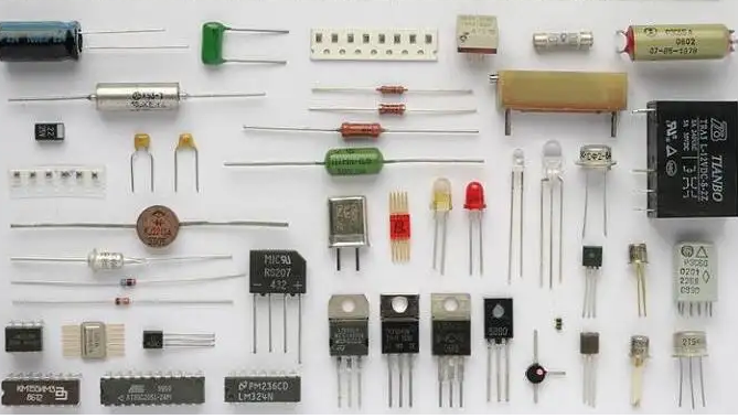
Seicheamh bioráin ar líne de chomhpháirteanna leictreonacha
I gcás formhór mór na gcomhpháirteanna leictreonacha, tá polaraíocht acu, nó ní féidir na bioráin a shádráil mícheart. Mar shampla, a luaithe a bheidh an toilleoir leictrealaíoch táthaithe ar chúl, pléascfaidh sé nuair a bheidh sé fuinneamh. Go ginearálta, nuair a bhíonn innealra beathaithe uathoibríoch á úsáid chun comhpháirteanna an bhoird chuaird a chur le chéile, ní bheidh aon fhadhb ann maidir le comhpháirteanna mí-áitithe. Mar sin féin, mar gheall ar theorainneacha na monaróirí agus saintréithe na gcomhpháirteanna, ní féidir gach comhpháirt a ghreamú nó a chur isteach go huathoibríoch. Tá socrú láimhe coitianta ag teastáil le haghaidh claochladáin éagsúla atá suite ar an dromchla, cónaisc, ciorcaid iomlánaithe cuimsithe, etc. D’fhéadfadh go mbeadh fadhb na hearráide tionóil fós ag na gléasanna seo. Go ginearálta, déantar an deisiú de láimh, agus tá an nasc seo seans maith freisin ar fhadhb an táthú droim ar ais. Dá bhrí sin, is gá modh suite na gcomhpháirteanna a mhíniú agus an gaol comhfhreagrach idir pillíní comhpháirteanna agus priontáil scáileáin síoda ar an mbord ciorcad.
1. Toilleas
For the electrolytic capacitor installed in the aluminum through hole shown in the figure below, the positive and negative poles are generally represented by the long and short feet and the mark on the body. The long leg is positive and the short leg is negative. Generally, there are white or other stripes parallel to the pin on the shell of the negative side.
Tá an toilleoir leictrealaíoch ar an mbord ciorcad marcáilte go ginearálta le polaraíocht mar a thaispeántar san fhigiúr.
One method is to mark a “+” sign directly on the positive side. The advantage of this method is that it is convenient to check the polarity after welding. The disadvantage is that it occupies a large area of the circuit board. The second method is to fill the area where the negative electrode is located with silk screen. This polarity representation occupies a small area of the circuit board, but it is inconvenient to check the polarity after welding. It is common in occasions with high density of circuit board devices such as computer motherboard.
Go ginearálta marcáiltear toilleoirí tantalam atá suiteáilte trí phoill le “+” ar an gcorp ar an taobh dearfach, agus déantar idirdhealú breise ar roinnt cineálacha trí chosa fada agus gearr.
The marking method on the circuit board of this capacitor can refer to aluminum electrolytic capacitor.
Le haghaidh toilleoirí leictrealaíoch alúmanaim atá suite ar an dromchla. Is é an taobh atá brataithe le dúch an cuaille diúltach, agus tá an bonn ar an taobh cuaille dearfach chamfered go ginearálta.
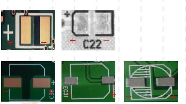 Ar an Bord Cuarda Clóbhuailte, it is generally shown in the figure above
Is é sin scáileán síoda “+” a úsáid ar an gclár ciorcad chun an cuaille dearfach a léiriú, agus imlíne an fheiste a tharraingt ag an am céanna. Ar an mbealach seo, is féidir an taobh chamfered a úsáid freisin chun an leictreoid dhearfach a aithint.
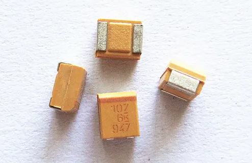
Toilleoir tantalam atá nasctha le dromchla
2. Dé-óid
For light-emitting diodes, the long and short pins are generally used to represent the positive and negative poles. The long pin is positive and the short pin is negative. Sometimes the manufacturer will cut off a little on one side of the LED, which can also be used to represent the negative electrode.
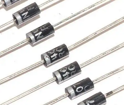
Úsáidtear scáileán síoda “+” go ginearálta ar an gclár ciorcad chun an leictreoid dhearfach a léiriú.
Le haghaidh dé-óid gnáth
Sa fhigiúr thuas, is é an taobh clé an cuaille diúltach agus is é an taobh dheis an cuaille dearfach, is é sin, úsáidtear priontáil scáileáin síoda nó gloine dhaite chun an polaraíocht dhearfach agus diúltach a léiriú. Úsáidtear an dá mhodh seo a leanas go ginearálta chun an polaraíocht dhearfach agus diúltach a léiriú ar an mbord ciorcad.
Tá polaraíocht an dé-óid léirithe ag an scáileán síoda ar an mbord ciorcad. Tá sé seo níos beoga. Is é an ceann eile ná siombailí scéimreach dé-óid a tharraingt go díreach ar an scáileán síoda phriontáilte chuaird.
The polarity representation of surface mounted LED is very confusing. Sometimes there are various representations between different package types in a manufacturer. However, it is common to paint color spots or color strips on the cathode side of light-emitting diodes. There are also corners cut on the cathode side.
The polarity of the diode is indicated by the silk screen on the circuit board. This is more vivid. The other is to draw the schematic symbols of diodes directly on the silk screen printed circuit board.
The polarity representation of surface mounted LED is very confusing. Sometimes there are various representations between different package types in a manufacturer. However, it is common to paint color spots or color strips on the cathode side of light-emitting diodes. There are also corners cut on the cathode side.
Úsáideann dé-óid mount dromchla gnáth freisin priontáil scáileáin síoda nó gloine dhaite ar an gcorp chun an leictreoid diúltach a léiriú
Ciorcad iomlánaithe
For dip and so packaged integrated circuits with pins distributed on both sides, the upper semicircular notch is generally used to indicate that this direction is above the chip, and the first pin on the upper left is the first pin of the chip. It is also indicated by a horizontal line on the top with silk screen printing or laser.
Ina theannta sin, tá poncanna scáileáin síoda go díreach ar an gcomhlacht in aice leis an gcéad bioráin den sliseanna nó brúigh pit go díreach le linn mhúnlú insteallta.
Léirítear roinnt ciorcaid chomhtháite freisin trí chiumhais beveled a ghearradh ar chorp imeall tosaigh an chéad bhioráin.
The symbols of this kind of integrated circuit on the circuit board are generally marked with a gap on the top.
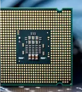
Le haghaidh QFP, PLCC agus BGA i bpacáiste tetragonal.
QFP packaged integrated circuits generally use concave dots, silk screen dots, or silk screen printing according to the model to judge the direction on the body corresponding to the first pin. Some use the method of cutting off an angle to represent the first foot. At this time, the counterclockwise direction is the first foot. It should be noted that sometimes there are three pits on a chip, so a corner without pits corresponds to the lower right of the chip.
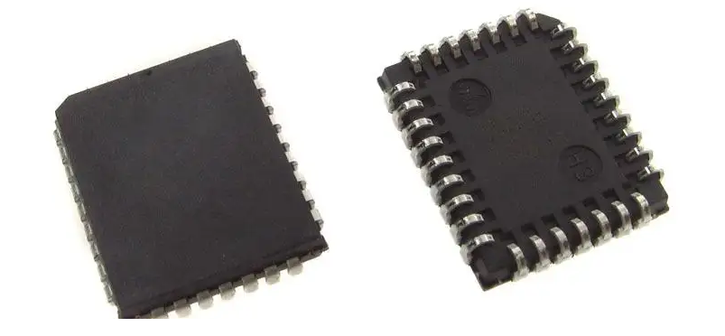
Because the body of PLCC package is relatively large, it is generally represented by pits directly at the beginning of the first pin. Some also cut corners at the top left of the chip.
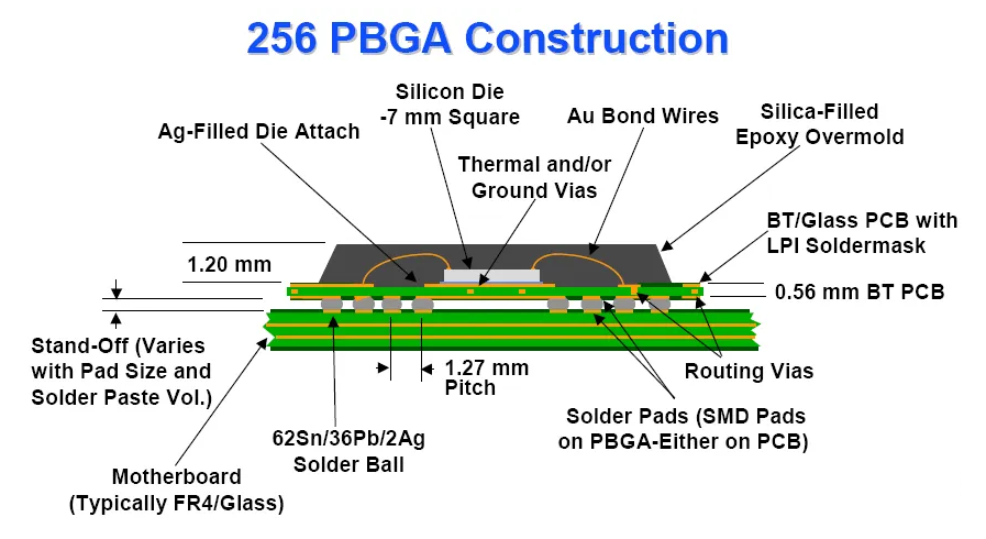
Réad pacáistithe BGA
Ní hamháin go n-úsáideann pacáistiú BGA an scragall copair órphlátáilte sa chúinne íochtarach ar chlé chun an chéad bhioráin a léiriú, ach úsáideann sé freisin coirnéil ar iarraidh, claiseanna agus poncanna scáileáin síoda chun treo an chéad bhioráin a léiriú.
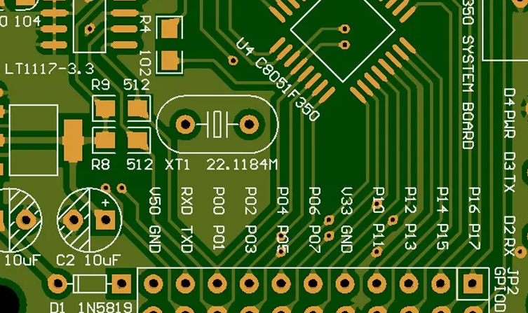
Is iad seo a leanas na grafaicí ar an mbord ciorcad comhfhreagrach
 The first leg is treated with silk screen dots and missing corners.
4. other devices
Sa réad fíor, rialaíonn an cónascaire go ginearálta an treo tríd an notch a shuíomh. Tá daoine ann freisin a scríobhann 1 in aice leis an gcéad chos nó a úsáideann triantán chun an chéad chos a léiriú. Go ginearálta, seachnaíonn gléasanna eile cur isteach mícheart trí scáileán síoda a tharraingt i gcomhréir leis an réad fíor ar an phriontáilte chuaird.
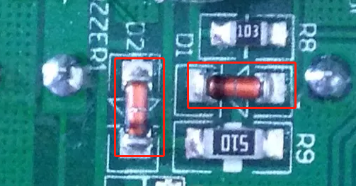
Chun an fhriotaíocht a bhaint as suiteáil trí-poll, cuirtear in iúl go ginearálta é tríd an deireadh coitianta a fhilleadh le scáileán síoda ar an mbord ciorcad. Nó scríobh 1 in aice leis an gcéad chos.
In order to standardize the requirements of pad, silk screen printing and resistance welding of components on circuit board, IPC organization has issued two related standards: ipc-7351 and ipc-sm-840. However, in actual use, the device direction marking symbols made by the device direction representation method defined by IPC are often blocked by the device body after welding, which is not suitable for inspection. The graphic design of component pad should be adjusted according to the actual situation.
In short, in real objects, generally discrete devices use the methods of long and short feet, silk screen printing or coloring to represent the polarity. For integrated circuits, concave points, silk screen printing, notches, missing corners, missing edges or direct indication are often used for the first pin marking. When making pad graphics, generally draw according to the device shape as much as possible, and reflect the information related to positioning on the device shape in the form of silk screen as much as possible, so as to avoid errors in manual assembly and welding.