
- 01
- Feb
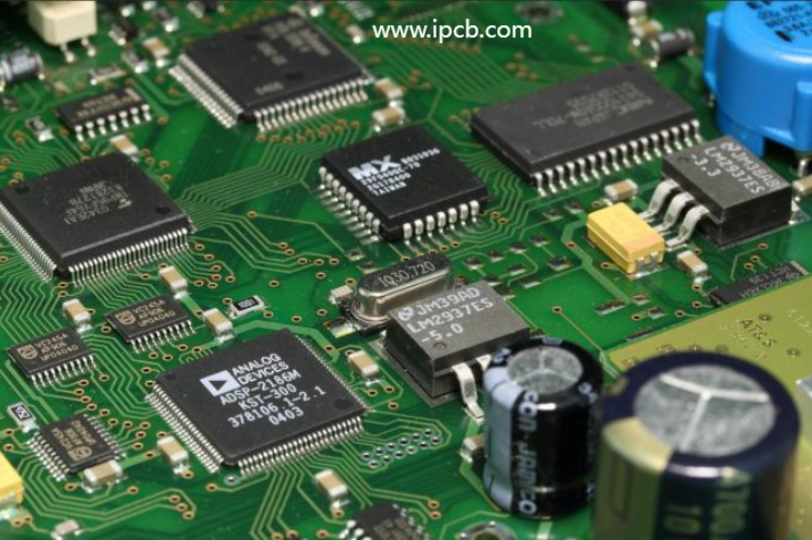
Mastering the Art of Surface Mount Printed Board Design
Introduction
In the fast-paced world of electronics, the design of surface mount printed boards (SMT) is a critical factor that directly impacts the reliability and performance of electronic devices. As technology advances, so do the complexities involved in creating efficient and reliable SMT designs. In this comprehensive guide, we’ll delve into the key design requirements, offering detailed insights for both novice and seasoned PCB designers.
1. Surface Mount Printed Board Shape and Positioning Design
a. Precision Matters
The shape of the printed board plays a pivotal role in ensuring accurate assembly and reliable soldering. CNC milling is the preferred method, providing a precision of ±0.02mm. For smaller boards, paneling is advisable, with careful consideration of placement machine specifications.
b. Positioning for Success
Precision doesn’t stop at shape. Positioning holes are essential for maintaining accuracy during the printing process. Consider the placement machine’s requirements and include adequate positioning holes for a flawless outcome.
c. Clamping Edge
To facilitate the welding process, a process clamping edge is recommended. If size constraints arise, consider adding a frame around the periphery, allowing for manual removal post-welding.
2. Wiring Method of the Printed Board
a. Keep it Short and Sweet
Minimize signal path lengths, especially for small-signal circuits, to reduce resistance and interference. When changing signal line directions, opt for diagonal routes rather than right angles to maintain signal integrity.
b. Trace Width and Center Distance
Consistency is key; maintain uniform width and center distances for optimal impedance matching. While thinner lines and smaller spacings are possible, balance these factors against manufacturing challenges.
c. Power and Ground Considerations
Wider wiring areas for power and ground lines reduce interference. Shield high-frequency signal lines with ground wires for improved performance.
d. Multilayer Wisdom
Separate power, ground, and signal layers in multilayer boards to minimize interference. Keep lines of adjacent layers as perpendicular as possible to reduce coupling and interference.
3. Pad Design Control
a. Size Matters
Choosing pad sizes that match component shapes and packages is crucial. Ensure symmetry in pad design for components like QFP and SOIC to enhance soldering reliability.
b. Land Length and Width
Prioritize pad length over width for reliable solder joints. Optimal sizes for L1 and L2 contribute to good meniscus profile formation during solder melting.
c. Lines Between Pads
Avoid crossing wires between pads of fine-pitch components; use solder masks for reliable shielding when necessary.
4. Benchmark Standard (Mark) Design Requirements
a. Fiducial Marks
Set fiducial marks on the PCB for placement machine reference. Tailor the size and shape based on machine specifications. For multi-pin components, add fiducial marks near pad patterns for optical positioning.
5. Other Requirements
a. Transition Hole Treatment
Avoid transition holes in pads, and maintain a distance of at least 1mm from the pad edge to prevent soldering issues.
b. Characters and Graphics
Steer clear of printing characters and graphics on pads to ensure optimal soldering.
6. Concluding Remarks
As a surface mount PCB design technician, a holistic understanding of circuit design and production processes is crucial. Mastery of SMT design is not just theoretical but practical, ensuring the quality of the entire production process.
In conclusion, surface mount printed board design is a vital link in the quest for superior electronics. By adhering to these design requirements, PCB designers can elevate the reliability and performance of electronic devices, contributing to advancements in technology. Remember, precision, consistency, and attention to detail are the keys to mastering the art of SMT design.